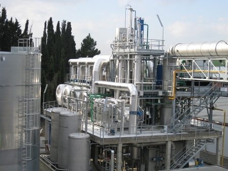
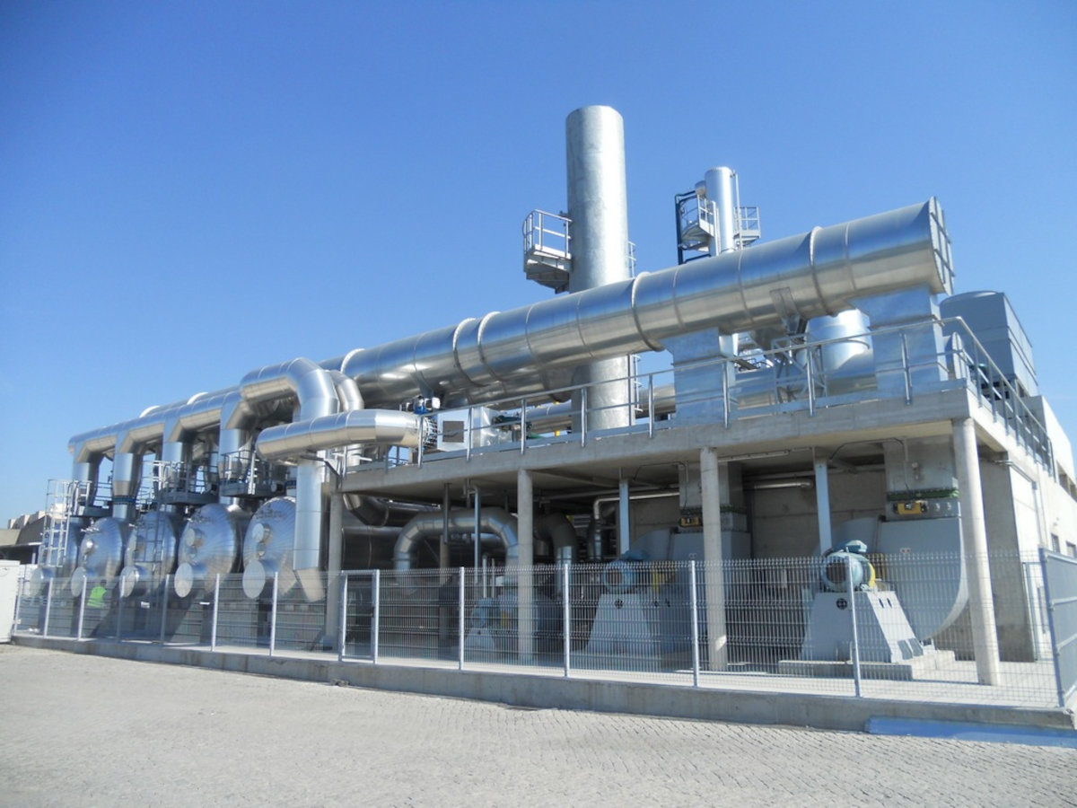
Solvent recovery plants are units for the purification of the gaseous emissions containing VOC (Volatile Organic Compounds) which have a double function:
- To abate the pollutant content in the emission, through adsorption on activated carbon beds;
- To recover the solvents captured by the carbon through specific regeneration.
When applicable, this technology therefore has a significant advantage, as it is beneficial not only from an environmental standpoint but economical as well, with quick payback (even three years). Brofind’s long-standing experience in the sector allowed us to install solvent recovery plants in a variety of industrial fields (printing, flexible packaging, adhesive tape, chemical, etc.) with treatment potential ranging from 2,500 to 300,000 Nm3/h of air. Depending on the nature of the recovered solvents, there are two different types of plants according to the technique used to regenerate the activated carbon:
- Steam regeneration: for non water soluble solvents (e.g. hexane, toluene), steam regeneration makes it possible to implement simpler and more economical plants;
- Inert gas regeneration: for water soluble solvents (e.g. ethyl acetate, ethanol), it is generally preferable to use nitrogen to regenerate the activated carbon.
Features and advantages
- Turnkey supply;
- Tailor-made design and optimisation of the plant according to the customer’s requirements, on a case-by-case basis;
- Selection of the materials used based on the application and the involved solvents;
- Customised design in case of reduced space available;
- Control panel with PLC for automatic management of the plant, designed for remote monitoring services.
Operating principle
Inert gas regeneration recovery plant
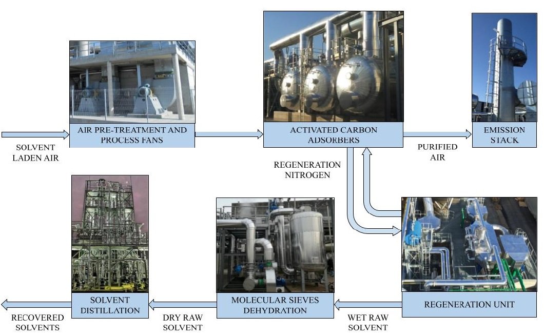
The solvent recovery plant with inert gas regeneration is suitable for solvents that dissolve in water as the recovery is carried out through condensation of the solvent. This technology is based on the following operating cycle: Pre-treatment and extraction The solvent laden air coming from the production cycle and extracted by the main fans, must first of all be filtered to eliminate any solids therein through the installation of a suitable filtering system. The flow rate of the air extracted from the plant is normally adjusted by inverters applied on the main fans, in turn managed by a pressure controller located upstream of the plant: this system allows for considerable energy-saving when the air flow rate is below the design value. A cooling unit then brings the air to a temperature suitable for adsorption, below 60°C, as this is more efficient at low temperatures. The temperature is only one of the parameters to be assessed, as special attention must also be paid to the moisture of the emission: over 60-70%, the amount of water adsorbed by the carbon increases exponentially, thereby reducing its efficiency and leading to malfunctions. Adsorption The polluted air flows in specific adsorbers in which an activated carbon fixed bed captures the solvent; the purified air can then be released into the atmosphere through the stack. Each plant is supplied with several adsorbers working in parallel. Each of them is kept in the adsorption phase as long as the outgoing TOC (Total Organic Carbon) concentration complies with the pre-established limit; when this value is reached, the saturated adsorber is then placed in the regeneration phase. Using an analyser to monitor TOC (Total Organic Carbon) concentration automatically optimises plant operation, activating regeneration only when the limit is reached at the stack; this way consumption can be reduced to a minimum according to the actual incoming solvent load.  Inertisation When the carbon is saturated, the adsorber is intercepted and inerted with nitrogen (to avoid the risk of the formation of explosive atmospheres). This phase continues until the oxygen content reaches a value sufficiently lower than the LEL of the mixture. Regeneration When a sufficiently low oxygen content is reached, the adsorber undergoes regeneration, during which the nitrogen continues to circulate in a specific circuit. A dedicated coil located upstream of the adsorber, fed with diathermic oil, heats it to approximately 200 °C. This way the high-temperature gas is capable of removing the solvent from the activated carbon, making it available again for the next adsorption phase. The nitrogen containing the solvent is then cooled in a cooling coil, fed with tower water. When the solvent concentration in the circuit, monitored by a specific analyser, reaches a pre-established value, it begins condensation in a second coil fed with chilled water. Two coils located upstream and downstream of the condensing coil, fed with glycol water in a closed loop, perform significant heat recovery on the unit. The recovered solvent can thus be transferred to intermediate storage to then be sent to the following dehydration and distillation sections, as needed. Dehydration – Condensation The first step towards reducing the water content in the solvent takes advantage of the fact that, during the carbon heating phase, water is released before the solvent, in only partially overlapping periods. Then most of the water can condense in a dedicated coil, to then be re-evaporated and reintroduced into the stream entering the recovery plant. With this system, solvent with a moisture content of 1-1.5% is obtained in the main condensing coil thus guaranteeing ideal operation in the following dehydration system on the molecular sieve. Dehydration – Molecular sieve The second solvent dehydration step is normally carried out through the adsorption of water on a molecular sieve, in the liquid stage. The condensed (moist) solvent is supplied to an adsorber capable of selectively capturing the water, thus guaranteeing solvent (dry) production with less than 0.5% water content. This unit is periodically regenerated with a hot gas stream, exploiting the same carbon regeneration circuit or with a dedicated circuit. Through implementation of the water condensing coil described in the previous point, a significant amount of energy is saved due to less frequent regeneration of this unit. Distillation As is often the case, for the plant to recover a mixture of solvents, a distillation section of the solvents might need to be installed to separate them one from another and to remove any impurities. This unit is always custom designed on a case-by-case basis, in order to optimise performance and to guarantee the best cost-benefit ratio. Brofind technology provides the following options:
- Batch or continuous operation;
- Configuration on single column or on several columns in series, working at different pressures;
- Implementation of heat recovery units.
Services provided
Choosing Brofind means:
- Customer assistance 24/7
- Impartiality in recommending pollution control technologies since Brofind is owner of many of them
- Experience in the design and manufacturing of abatement plants since 1993
See the page dedicated to Brofind services to understand how we support our customers during the entire lifecycle of the product.


